Zero Cross Detector
A zero cross detector is used to detect the moment when the mains line changes its polarity (i.e. the voltage is close to 0 V). This may be useful to fire a SCR at the right time, or simply to get a time base with the accuracy of the mains frequency.
In most cases, this will be just a series circuit of a resistor and an optocoupler.
To get a useful signal level, the current has to be several mA and causes a power dissipation of several Watts, resulting in voluminous resistors and significant heat development. The zero crossing can only be detected approximately (maybe corrected by software in some cases). Here we see a circuit which makes that much more effective and accurate.

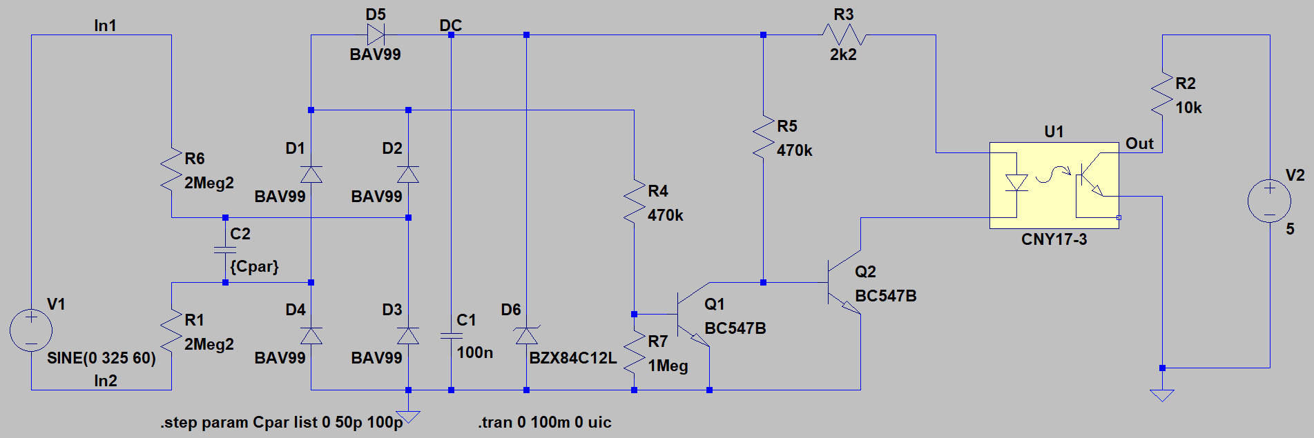
Here the Download of the circuit.
The two 2.2 MΩ resistors consume only 12 mW (together, each of them only 6 mW!).
They charge the 100 nF bulk capacitor
, which is big enough to give a short pulse over the optocoupler. Every falling edge tells your microcontroller, now we have zero!
Obviously, the circuit is significantly more complex than a simple series resistor plus a protection diode, but since we're talking about a 2 W resistor here and all the components are SMD, the area requirement is put into perspective. A BAV99 contains two diodes, so we only need two of them, not four, etc.
The energy savings are certainly considerable!
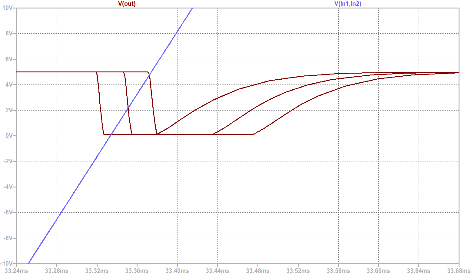
 Due to the extremely high resistor values parasitic capacitances as low as 100 pF (Cpar in the circuit, in the graph you see values of 0 pF, 50 pF and 100 pF) can have an impact to the result but we are still better than the circuit with a resistor and an optocoupler.
The ZVD pulse arrives still within 0±5 V (at 650 V VSS), very close to the zero crossing, less than 1° in phase.
In real life, you may even want to add 50 pF or so to improve noise immunity.
This circuit was made for european mains of 230 VAC. For 110 VAC the input resistor values may have to be lower to guarantee the function. Just simulate it!
Take a look at the maximum working voltage of the resistors! Depending on the size, you may have to use a series connection of several smaller ones! If you use THT 0207 they may be good. When using 1206 it gets hairy, if you use 0603 you would have a series circuit of at least 6×680 kΩ! If in doubt, take a look at the datasheet of the manufacturer.
Additionally also consider transients and surges the circuit must withstand according to current EMI standards.
In the simulation, a resistor withstands any condition, in reality you have to follow the datasheet values and keep appropriate clearance to prevent sparking.
Be careful what you touch, use a safety isolation transformer for experiments. We are working with mains voltage!
This is just a simulation. I have never built this circuit in reality. Use at your own risk and responsibility.

