Spice Model of a Relay
 Here I tried to simulate an electromechanical relay as close to reality as possible.
Note: this model was written for LTspice and will probably only work in LTspice since LTspice intrinsic models like SCHMITT, AND etc. may not exist in other spice derivates.
A note about the circuit: it does not contain a voltage source nor a simulation command, you cannot just click run
. It is the circuit of the model. Voltage source and simulation command have to be inserted in the superior circuit.
Please also note that the relay is polarized. If the coil voltage is reversed, it will not pick up! Therefore, it is not directly suitable for AC excitation.
I've modelled the following parameters:
- Rcoil: Coil resistance
- Lcoil: Coil inductance
- Von: Must operate voltage
- Voff: Must release voltage
- Ron: Contact resistance
- Roff: Isolation resistance
- Tdelay: Delay time (the time from applying coil voltage until opening of the break contact)
- Tfly: Contact fly time (time from opening the break contact to closing the make contact (
break before make
)). Note: this time cannot simply be chosen negative in order to implement a follow-up changer (Make-before-Break
)!
Especially, I did not try to model contact bouncing.
To explain: You apply the coil voltage. <Tdelay> later, the NC contact opens. From then on,
neither contact is closed. After a further time, <Tfly>, the NO contact closes,
and the switching process is complete.
When the coil voltage is removed, the process is reversed. After <Tdelay>, the NO contact opens, and after a
further time <Tfly>, the NC contact closes again
and the relay has dropped.
<Von> is the minimum voltage for the coil to turn on and the coil voltage has to drop below <Voff> for the relay to turn off again.
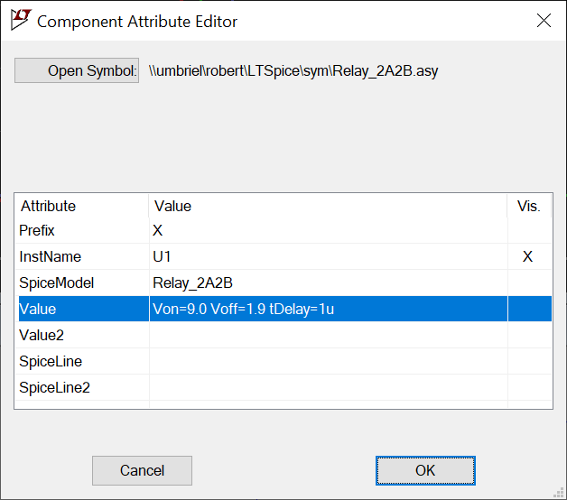
 The defaults correspond (except some estimated values you cannot find in the datasheet) to a Schrack SR4D with a 24 V coil, but you can override these with your own values (right-click on the relay symbol and you will see the window in the right picture. There you can enter your parameters (blue line, just as an example)).
Of course, the values here are also idealized to a certain extent. In reality, the relay can also pick up at a lower voltage or release a little earlier.
If the coil voltage changes slowly (which should be avoided anyway) this may become relevant, but the model should reflect all relevant parameters for most cases.
The purpose of this relatively sophisticated simulation was to create a circuit with functional safety
, in which the switching state of the relay had to be monitored depending on its control. Auxiliary contacts of the forcibly guided contact relay were fed back into the electronics.
A relay stuck in the off position is simulated by interrupting the coil supply, a relay stuck in the on position by bridging the switching transistor.
This is the only way to reliably simulate the influence of the mechanics with its switching times on the electronics. This is the only relatively easy way to check what happens if a contact is oxidized (i.e. there is no conductive connection despite a closed contact) or it is simply stuck (welded), i.e. the relay cannot switch at all.
However, the model can of course also be used for simpler purposes or just for demonstration.
Download the LTspice circuit or download the model and symbol for direct use in your own simulations.
Just copy the model to your sub-directory and the symbol to your sym-directory and you can use it directly in your own simulations.

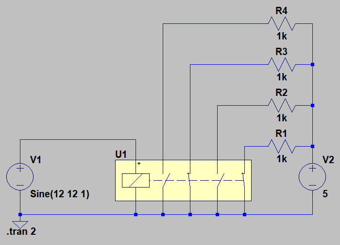
 In this test simulation, you can watch the actions of the contacts. This of course requires a correctly installed sub and asy. The relay is driven by a low speed 1 Hz sine voltage, and you can see when it operates, when it drops, and you see the non overlapping contact actions (break before make).
And now with bouncing...
 I have developed the model further so that the bouncing of the contacts can also be shown.
Of course, the bouncing can only be behavioral
and not the image of a specific component, since in addition to random components it also depends on many other parameters such as temperature, aging, switching voltage, installation position, etc..
A warm relay bounces differently than a cold one, a new one bounces differently than an old one, a relay near an airplane engine while the airplane is doing a loop bounces differently than the same relay on your lab bench, etc. If you want to simulate bouncing, simply set the worst-case values here. If there's less bouncing in reality, this is usually not a problem.
I moved this extension to a separate project because modeling it is considerably more complex and rarely of any importance. In most cases, bouncing can be sufficiently taken into account through theoretical considerations.
With my model, bouncing only occurs when a contact is closed. In fact, this is also the case in reality. When opening, the contact does not bounce or hardly bounces.
Imagine the beater of a drum hitting the surface.
It will hit the surface repeatedly and then bounce back again, that's the bounce,
the brrrrom
of a drum. When it lifts off, it will leave the surface without
touching it again, and there will be no audible sound.
The contacts open after <Tdelay> without bouncing.
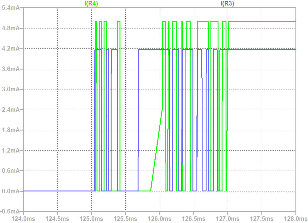
I have used two noise sources here so that the contacts do not bounce synchronously, as can be seen on the oscillogram.
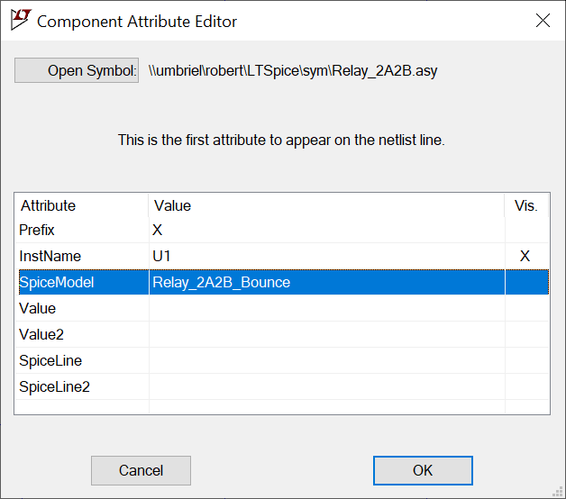
 Here is the circuit as a running simulation, the model is already included in the current model file, and the corresponding test circuit, which is otherwise identical to the previous one. You just need to replace the relay's spice model with
 Relay_2A2B_Bounce
.
This model has an additional parameter that you may want to adjust:
- Tbounce: the bouncing time
Known Problems
Due to the simple input circuit with a Schmitt trigger, even very short pulses are sufficient to cause the relay to be activated, as long as the voltage does not drop below the must release threshold. Therefore, check the coil voltage or power to see whether it is really sufficient to operate!
In order to alleviate the problem of short spikes (as they often occur in simulations) C1 and R2 were added to the model, but they still do not produce a reliably realistic function.
Here we have a behavioral model, that in principle reflects the most important properties, but cannot be a model of a specific component.
In most cases this will not be a problem as the coil will either receive full voltage or none at all.
2025-10-10: Until this date, the model generated a warning in newer LTspice versions. However, this warning was non-critical and did not prevent correct functionality. I have since corrected the model accordingly, and this warning should no longer appear in the current download.
This is just a simulation. I have never built this circuit in reality. Use at your own risk and responsibility.

