
Energy saver for Relay Coils
For a normal monostable relay, it is absolutely sufficient to supply the necessary must operate current just until it is on. After that, a much lower current is enough. In most cases, 30..50% of the must operate current (or voltage) is safe.
 You can do this in an analog way what would increase the total power dissipation, or you can take advantage of a PWM. In the circuit here, R1 must be selected according to the resistance of the relay coil.
C1 must be big enough to ensure a safe operating pulse.
Additionally, it should be noted that it takes about half a second after switching off for C1 to be sufficiently discharged through R1, i.e., for the circuit to be
You can do this in an analog way what would increase the total power dissipation, or you can take advantage of a PWM. In the circuit here, R1 must be selected according to the resistance of the relay coil.
C1 must be big enough to ensure a safe operating pulse.
Additionally, it should be noted that it takes about half a second after switching off for C1 to be sufficiently discharged through R1, i.e., for the circuit to be armed
again.
If you had a microcontroller, this would be no problem. Connect the relay to a PWM output and you can do what you want. But you can do this also with directly controlled relays... with only one cheap IC, a 4093 (quadruple NAND gate with schmitt trigger inputs)!
So you can lower the power dissipation of the relay coil to 25%, if you lower the duty cycle to 30% even down to 10%!
 Here is my circuit, which does this with a single IC, a cheap 4093, plus a few resistors, two capacitors and two diodes at minimum cost. It should be mentioned that there are ICs like the DRV103), which make this with lower board space, but for ten times the price. But also in availability, the 4093 is probably in advance. A 4093 you can always get from some source but if you read,
 Not in stock, delivery time 46 weeks
if you look for the DRV103, things might get tight.
The circuit is about the left half, the rest shows the relay and means to measure the coil voltage and ‑power.
R1 and C1 create the time for the operate pulse, which is digitized by A5 and A2 (indeed only one gate of the 4093, A5 is only necessary because there is no NAND with schmitt trigger inputs in LTspice).
The circuit around A3 and A4 (again a single gate) produces the clock for the PWM, the duty cycle of which can be lowered by D3 and R6 at will. In the configuration shown, it is about 40%.
Finally, A6 (which needs two gates of the 4093 since we have to invert the NAND signal, adds all together.
The clock frequency must be high enough so that the coil current will not drop to 0. Only then we can lower the coil power dissipation to a quarter (or even lower).
 In my simulation, C2 is much too big, but this accelerates simulation speed and is better suited to show the effect. In reality, C2 should be about 4.7 nF for not to drop the coil current to 0 and not to produce audible noise.
The actual value has to be checked in the real circuit since we use behavioral models
here, that only show approximately the actions of a 4093. The same is for the duration of the operate pulse. This is quite long here at around one second, but we have nearly no heat dissipation in this time and you can be sure that any relay is fully energized. If necessary or wanted, you may of course shorten it by lowering C1.
Of course, the simulation will also work with 4.7 nF, but the simulation time significantly increases. (we may talk about minutes then). But you can read out the coil power (VPow, 1 V≙1 W) ant the effective coil voltage (VRelAvg). You should take the time to do this for the final simulation!
 Transformed to the four NAND Schmitt Triggers of a 4093 (or maybe a 74xx132) the circuit looks like depicted here. Schmitt Trigger inputs are important since we are working with analog signals on the two RC circuits. I must emphasize that I never built this circuit in real life and this is just a simulation.
In my situation, I had four relays with 800 mW coil power each inside a relatively small housing. This makes 3.2 W, which would raise the inner case temperature about 30°C (measured) above ambient temperature. At an ambient temperature of 50°C we would reach 80°C! Respecting the maximum junction temperature of 150°C this may not become critical but at some point, your enclosure will simply begin to melt!
I've modified the circuit slightly compared to earlier versions. Connecting U1.1 to In stops the oscillator as long as the relay is off. The improvement may be minimal (slightly lower power dissipation, slightly less EMI), but it simply feels better this way. Nobody likes working for the trash can. Not even an oscillator 😉.
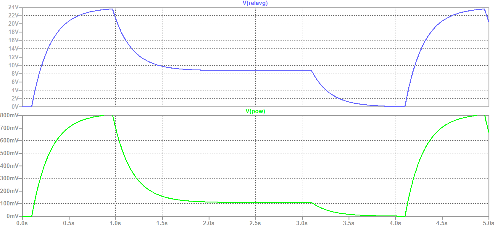 With this circuit, you can bring down power dissipation to about 1/8 and lower the temperature rise to below 5°C (not verified up to now), the relay would still keep securely operated. In the graph, you see the lowered coil voltage and respectively the coil power (1 mV corresponds to Pow=1 mW) which is about 1/8 compared to full voltage.
The PWM frequency has to be in kHz range (the current through the coil must not sink to 0) else the power dissipation will only be multiplied by DC (the relay simply switches on and off) and not by DC²!
Recommendable is a frequency of more than 20 kHz to eliminate audible noise. In industrial environment, this sometimes may be ignored. Don't matter if it beeps or hums, hopefully it just works...
EMI shouldn't be a hard problem here, since fast changing current is not possible in a highly inductive circuit (the relay coil).
But take care for a low impedance connection of Q1 since it will carry rapidly changing currents (place the collector close to the relais and connect the emitter directly to the ground plane) as well as the free-whelling diode since it takes the current rapidly from the switching transistor.
This is just a simulation. I have never built this circuit in reality. Use at your own risk and responsibility. Especially in environments with high vibration or high g-forces the relay might drop while keeping operational on the lab bench. Always verify your circuit in reality!