Short circuit proof Relay Driver
Normally you would simply use a NPN transistor (or a N channel MOSFET) which is protected by a zener diode or a freewheeling diode against VCC from the self induction voltage of the relay. This would work reliably in 99% of all cases. If there was a production failure, it will be detected while testing and at worst case, it will lead to replacing the destroyed transistor.
Sometimes, however, the relay will not be on my
PCB but be connected via external cable, and it may be an unknown relay according to the customer. It may well lead to overloads or short circuits which could damage the transistor.

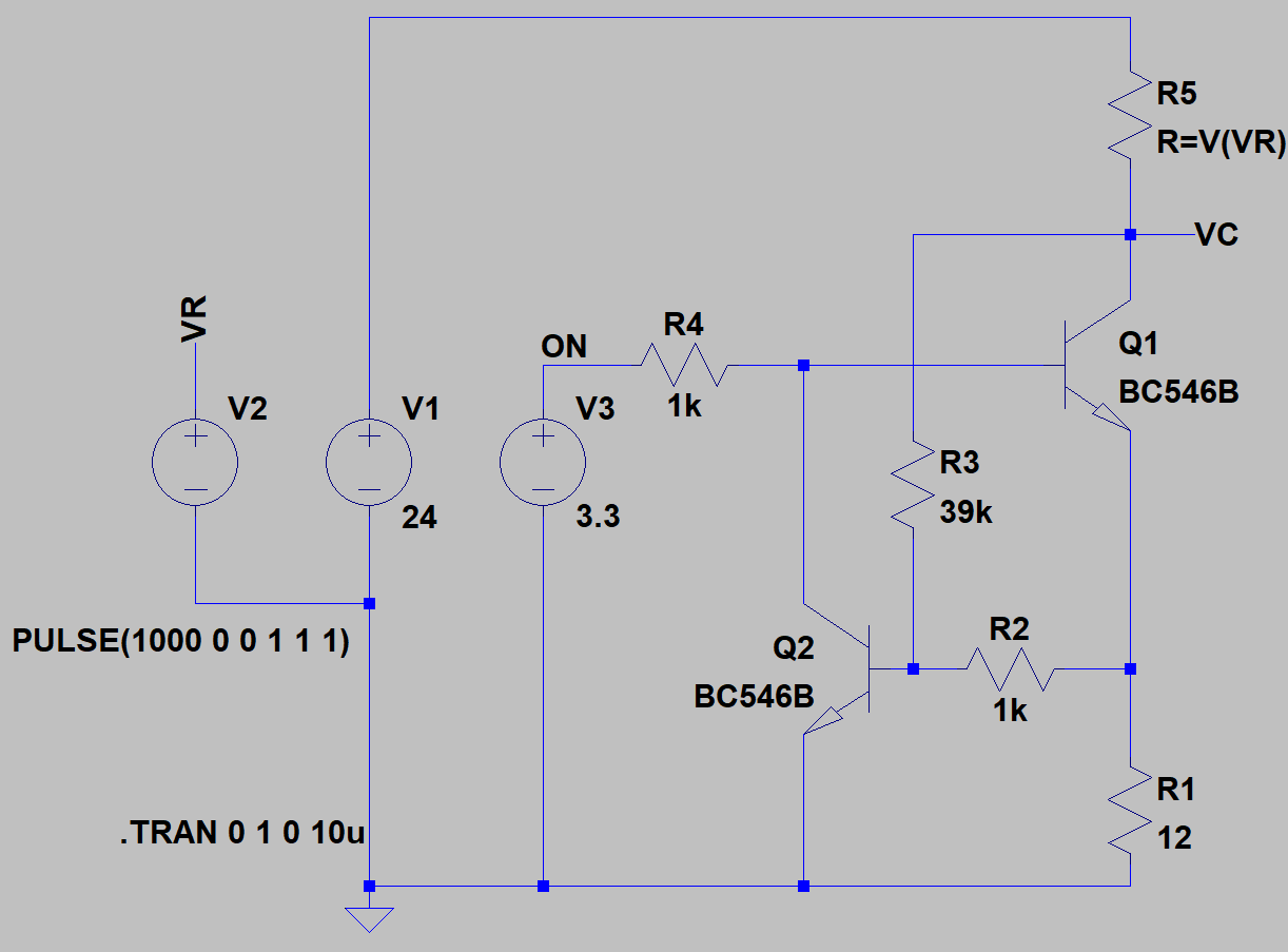
I made my thoughts about that and ended up in a circuit like a constant current source. The current is dependent on the collector voltage. Rising collector voltage leads to lower current to limit power dissipation. Without R3 we just had a constant current source (where R2 would not be necessary), together with this additional circuit it becomes a limiter circuit.
It takes an additional transistor and three resistors. It is your decision if it is worth it.
How to dimension this circuit?
In the following, I'll assume a 24 V supply and, accordingly, a 24 V relay.
- The voltage divider (R3+R5) and (R2+R1) biases the base of Q2. This voltage must be chosen so that Q2 (at VON=0 V respectively VC=24 V) blocks safely (i.e. <600 mV). R5 here is 0 Ω (the worst case, a short circuit).
- The maximum power dissipation of the transistor must never be so high that its maximum junction temperature is exceeded, regardless of the load, from ∞ to 0 Ω, even after any length of time. This sets a lower limit for the value of the shunt resistor R1.
With our BC546, having 200°C/W, the power dissipation must be kept below 400mW to keep heating below 80°C.
So the junction temperature will reach about 120°C on a hot summer day (~40°C), correspondingly more if the circuit sits in a housing together with other heat-producing components and a limited thermal resistance to Tamb.

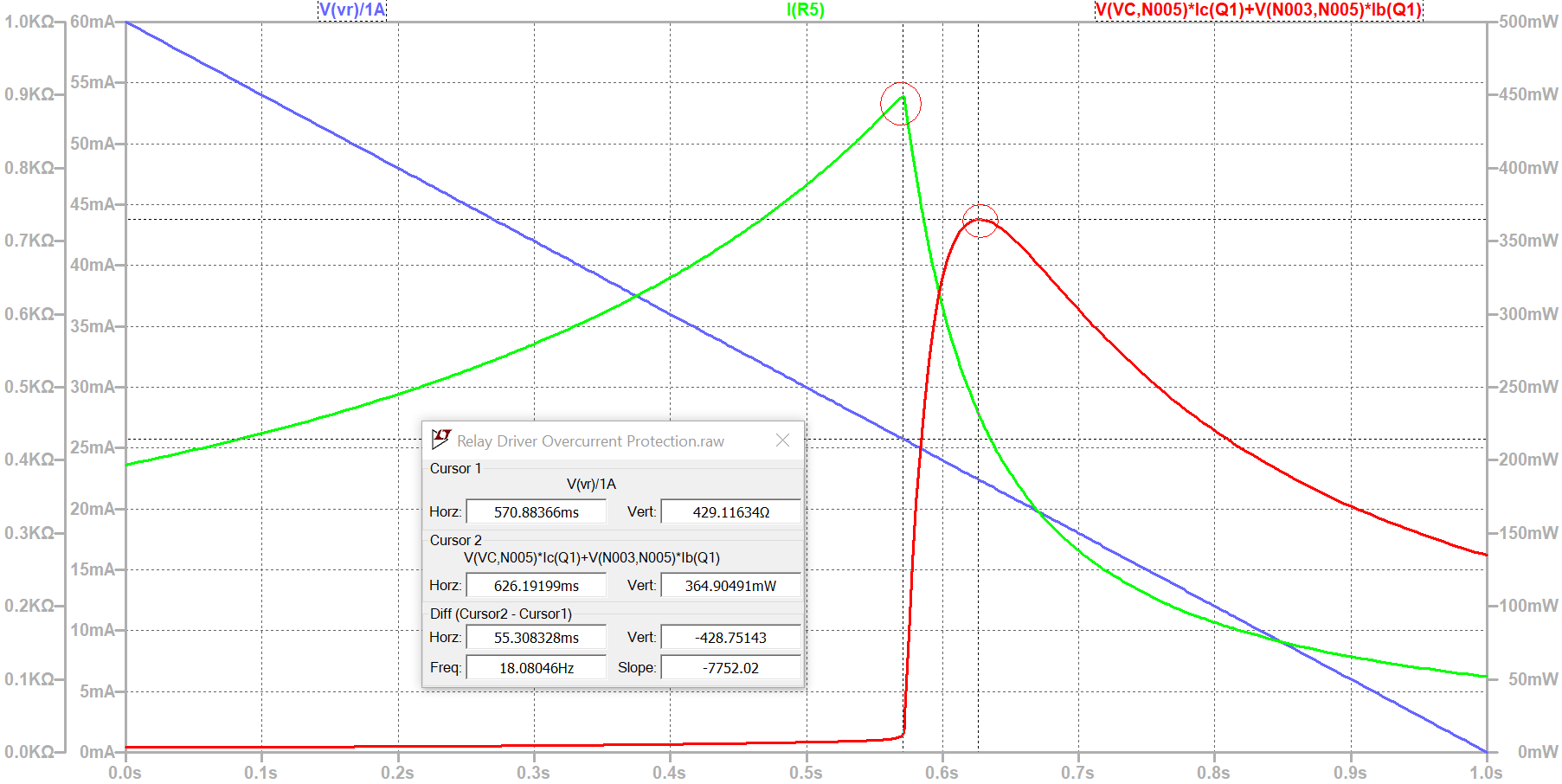
Green: coil current
Red: power dissipation of Q1
In this simulation, RLoad (R5) is reduced from 1000 Ω to 0 Ω at a supply voltage of 24 V. You can see the point at which the power source begins to regulate and limits the current through the relay. This is also the point at which the relay can no longer be switched reliably (cursor 1, the left red circle, at 430 Ω). The point of maximum power loss comes a little later and is here at 365 mW (cursor 2, the right red circle at 626 ms). The transistor already heats up by around 73°C, which is still well below the limit of 150°C even at an ambient temperature of 55°C and is therefore still in the safe range even in a cozy, warm electronics housing.
I simply adjusted the shunt resistor (R1) step by step until I reached this limit. Someone who is better at mathematics than me could certainly solve this formally, but in the simulation after a few iterations it is also possible for dummies like me.
24 V relays can be switched with this circuit down to 430 Ω. In practice, the coil resistance (component tolerances, temperature coefficients, etc.) would be set 10 or 20% higher so that the minimum permissible coil resistance according to the manual would be 540 Ω.
My relay was at 700 Ω (relatively low for a 24 V relay), so still not a problem.
Note that the maximum power dissipation point can be reduced by making R3 smaller, but at some point the circuit will not deliver any current at all! R3 should probably be at least 20% larger than this limit.
In other words, R3 must be at least as high so that Q2 at VC=V1 safely does not have an impact on the regulation, i.e. VB of Q2 must still stay below 600 mV at VC=V1!
So we now have a circuit that does not break even if an unacceptable load (including a short circuit) is applied. It may not work as expected under unacceptable loads, but it won't break! Of course, a freewheeling diode or other overvoltage protection is also required to limit the self induction voltage when switching off!
The additional costs are in the 10 cent range and should not be a problem in most cases. Admittedly, it takes up a bit of board space and the circuit designer has to think over it a bit more...
Normally I would also warn at this point: pay attention to the SOA of the transistor. Maybe this will throw a spanner in the works for us. But I didn't find any information about the SOA in the data sheet of the BC546 or a comparable small signal transistor. Maybe it actually doesn't matter? Only a practical test could provide certainty.
This is just a simulation. I have never built this circuit in reality. Use at your own risk and responsibility.

