7-Segment Reverse Bias
Many rookies (and also many professionals) are making a capital mistake by configuring the segment drivers (i.e. the port pins since normally there are no additional drivers here) as a push-pull (or totem-pole) output, meaning the pin is simply an output driving against Vcc or GND. Well, this works indeed, but not always and not always for a long time...
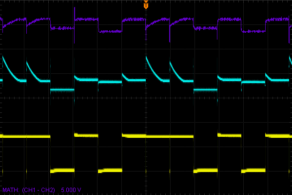
 In this picture, CH1 is
a segment and CH2 is a
CC of a display
(each directly the pin at the display, not at the controller!).
The math-
If we watch a digit currently driven, this is no problem but if you look at a digit that is 'off' you can see a reverse bias over some LEDs since the cathode driver is hi-Z and segments being driven low experiences a reverse voltage caused by other diodes that are forward biased (i.e. being lit on some other digit). This will not be full VCC but two or three volts might occur.
This is why we should drive the digit only against GND (what the ULN2803 does perfectly) and the segment only against VCC but not against GND! The solution is not to use the PORTx but the DDRx. We switch the PORT permanently high and only the DDR decides, wich segment gets some current.
With current 7-Avoid reverse bias by design
i.e. reverse voltage is simply inacceptable
and could cause anything from reduced brightness over reduced endurance up to
immediate failure.
The datasheet of our display also specifies a maximum reverse voltage of 5 V
but it also states Prolonged reverse bias should be avoided...
.
You cannot decide if the short times of reverse voltage in multiplex-
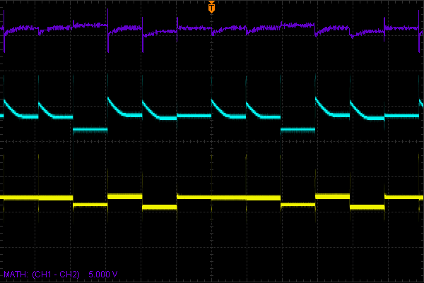
 In the second picture, the PORT is permanently '1' and only the DDR is switched.
You can see the segment pin not longer driving against GND but only buckling down until the segment
draws no current.
As the math-
All signals now are in permissible range and that's how it should be. Additionally you can see much lower amplitudes in the steep signals what means reduced EMI, which is of growing importance nowadays.
Indeed, it showed to be advantegous to keep the pull-ups active. Their very low current makes no visible illumination of the segments switched off but reduces the reverse bias that would otherwise build up over the junction capacitance of the LEDs.
The glitches you see on the math-

